10 Tips for 3D Modeling for 3D Printing

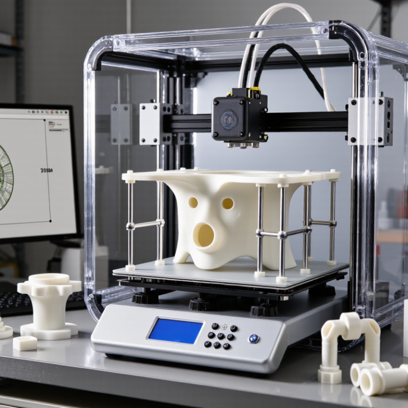
Turning a screen-based concept into a reliable printed object requires more than attractive geometry. 3d modeling for 3d printing connects digital design with material behavior, machine limits, and real workshop decisions. A model may look perfect in CAD, yet fail because its walls are too thin, its overhangs are too steep, or its holes shrink during cooling.

Chuck Hull, inventor of stereolithography, described the breakthrough simply: “You could make parts directly from digital data.” That idea still guides practical modeling today. Digital data must become physical evidence. A successful workflow considers print orientation, layer height, nozzle or resin settings, support removal, and post-processing before the file reaches the slicer.

Small details matter. A 0.4-millimeter nozzle cannot reproduce every sharp edge. A press-fit joint may need extra clearance. A tall, narrow column can wobble when each layer cools. These ten tips examine such decisions, from choosing a printable form to checking mesh integrity and testing tolerances with small prototypes.

Some assumptions will fail.

That is part of the process. Even experienced designers revise models after seeing elephant-foot distortion, weak bridges, or unexpected warping. Reliable results come from documented tests, measured changes, and honest evaluation rather than confidence alone. This guide combines established additive-manufacturing practice with practical observations from iterative modeling. It does not promise a perfect first print. Instead, it offers a disciplined path toward stronger, cleaner, and more predictable parts.

10 Tips for 3D Modeling for 3D Printing

Define the Print Goal: Material, Technology, Tolerance, and ISO/ASTM 52900

A successful 3D print begins with a clearly defined goal, not a beautifully detailed model. Decide whether the part needs visual appeal, mechanical strength, heat resistance, or accurate assembly. In my workshop experience, unclear goals caused more failures than poor CAD skills. A decorative prototype can accept visible layers. A functional bracket cannot.

Material and printing technology must support that goal. Rigid polymers, flexible materials, and metal powders behave differently during cooling and post-processing. Layer direction also affects strength. Select the technology according to surface finish, production volume, and available accuracy. Then test a small feature before printing the complete part. This step often exposes warping, weak walls, or unexpected shrinkage. It feels slower, but it saves material.

Tolerance needs a measurable definition. Do not write “high precision” without a target value. Specify dimensions, allowable deviation, critical surfaces, and assembly clearance. ISO/ASTM 52900 provides shared terminology for additive manufacturing processes and helps teams describe these decisions consistently. Use its language when documenting the process, but verify every tolerance through actual measurements. A standard improves communication; it cannot remove process variation. Small gaps matter. I still review failed prints carefully, because one overlooked corner or unsupported hole can reveal an unrealistic assumption.

Build for Process Limits: 0.2 mm Layers and 0.4 mm Nozzle Clearance

3D models for printing should respect the machine’s physical limits. A 0.2 mm layer height captures moderate detail, but it cannot reproduce features thinner than the deposited line. With a 0.4 mm nozzle, design walls at least 0.8 mm thick for reliable strength. Thin fins may appear in the preview and disappear on the build plate. That happened in one of my early prototypes.

Tip: Check every narrow feature in the slicer preview. If a wall receives only one weak path, enlarge it or redesign the geometry. Rounded corners usually print more consistently than sharp internal angles. They also reduce stress concentration.

Fit requires practical testing. For separate parts, begin with about 0.4 mm total clearance for a loose sliding fit, then adjust after printing. The correct value depends on calibration, material behavior, cooling, and the part’s orientation. Do not trust a perfect digital fit. It is only a guess. Add small chamfers to assembly edges, especially around holes and pegs. A 0.2 mm layer can create visible stepping on angled surfaces, so rotate critical faces when possible.

Tip: Print a small clearance test beside the final model. Measure the result with calipers, record the setting, and revise the CAD file instead of hiding the problem with force.

Optimize Geometry: 45° Overhangs, 1.2 mm Walls, and Rigid Ribs

For reliable 3D printing, geometry should respect how each layer is deposited. I usually keep unsupported overhangs near 45 degrees. This angle reduces sagging and limits the need for temporary support material. However, 45 degrees is not a guarantee. Cooling, layer height, and material behavior can change the result. Small tests matter. Print a short overhang ladder before committing to a large part. A 50-degree feature may succeed on one machine and fail on another.

Wall thickness also needs practical testing. A 1.2 mm wall often provides a useful balance between weight and stiffness. It may equal several printed perimeters, depending on the chosen line width. Avoid placing thin walls beside sharp internal corners. Those areas can warp or separate under stress. I add rounded transitions where possible. My first designs used uniform walls everywhere, but that wasted material and still produced weak joints. The better solution was selective reinforcement.

Rigid ribs can strengthen broad panels without making the entire model solid. Place them along likely bending directions, and connect them smoothly to the main wall. Keep rib bases wide enough to bond across several layers. Excessively tall ribs may introduce new overhangs or vibrate during printing. I sometimes reduce a rib after testing, even when the larger version feels safer. That revision saves time and weight. Measure the printed part, not only the digital model. Calibration errors, shrinkage, and slight layer shifts can change a precise fit.

10 Tips for 3D Modeling for 3D Printing: Optimize Geometry

Practical starting dimensions for FDM models using a 0.4 mm nozzle. A 1.2 mm wall or rib equals approximately three extrusion line widths, while a 45° overhang is a common starting point for reducing support requirements. Actual results vary with material, layer height, cooling, and printer calibration.

Add Reliable Features: 0.4 mm Gaps, 2.5 mm Holes, and Rounded Corners

Reliable features begin with realistic printer limits. For a common 0.4 mm nozzle, a 0.4 mm gap is only a starting point. Slicer overlap, cooling, and calibration can close it. I measure test coupons with digital calipers before designing snap fits. A 0.5–0.6 mm clearance often works better for moving parts, but material and print direction still matter. That detail is easy to underestimate.

A 2.5 mm hole may print undersized, especially through vertical walls. The toolpath must approximate a circle with limited extrusion lines. I usually print a small hole ladder, then compare the results with a 2.5 mm drill gauge. If the hole receives a pin, adding 0.2–0.4 mm can improve assembly. Do not assume every machine behaves alike. The 2024 Wohlers Report valued the global additive manufacturing industry at approximately $20.0 billion in 2023, showing how widely different processes and materials are now used. One universal tolerance chart cannot represent them all.

Rounded corners make models more forgiving. A 1–2 mm internal radius can reduce sharp stress points and help layers follow the shape smoothly. External radii also improve handling and reduce corner lifting on larger parts. ASTM International’s additive manufacturing guidance emphasizes process control and repeatable validation, not attractive geometry alone. My first test often looks acceptable, yet the final assembly feels tight. That is useful feedback, not failure. Revise the gap, hole diameter, or radius, then print again. Small experiments beat confident guesses.

Validate the Model: STL Accuracy, Mesh Repair, and Fit Testing at Scale

Before sending a model to print, validate the digital file as if it were a physical part. An apparently clean surface can hide flipped normals, gaps, or overlapping shells. Check units, wall thickness, and minimum feature size in the original design. Then export an STL and compare its dimensions with the source model. Measure critical locations, such as a 20 mm bore or a 2 mm slot. Small errors become obvious after printing.

Use a mesh inspection tool to reveal non-manifold edges, holes, self-intersections, and inverted faces. Repair one defect at a time, then inspect the mesh again. Automatic repair is useful, but it can close a hole incorrectly or erase a thin feature. I have seen a repaired file pass visual inspection and still produce a blocked channel. That mistake cost material and time. Keep an untouched copy for comparison.

Fit testing should happen before a large production run. Print a small test coupon containing holes, pins, snap joints, and mating surfaces. Record actual clearance with calipers, not assumptions. Different printers, materials, and layer heights change the result. At scale, test several units from different build positions. A single successful prototype proves very little. Log failures, revise tolerances, and repeat the test. Do not trust perfect software previews.

10 Tips for 3D Modeling for 3D Printing - Validate the Model: STL Accuracy, Mesh Repair, and Fit Testing at Scale
# Validation Area What to Check Practical Acceptance Guideline Recommended Test Typical Failure Prevented
1 Model Units Confirm that the CAD unit system matches the intended export and slicing unit. Verify at least one known dimension after STL import. STL files do not reliably store physical units, so the measured size must match the design intent. Export a calibration cube or a known reference feature, then measure it in the slicer and in the final print. Models printing 25.4 times too large or too small because of inch-to-millimeter confusion.
2 STL Resolution Check chord height and angular deviation used to approximate curved surfaces. Use a chord-height tolerance smaller than the visible surface requirement. For general parts, approximately 0.01–0.10 mm is a common starting range; avoid unnecessarily dense files. Compare the faceted STL with the original CAD model and inspect file size, curved edges, and slicer preview. Visible polygon facets, oversized files, slow slicing, or loss of small geometric details.
3 Watertight Mesh Identify holes, open boundaries, non-manifold edges, and zero-area faces. The mesh should contain closed shells with no open boundaries or non-manifold geometry before slicing. Run a mesh-inspection report and review highlighted errors in a mesh-repair tool or CAD validation environment. Missing surfaces, unexpected cavities, incorrect slicing, or failed toolpaths.
4 Normals and Shell Direction Verify that face normals point consistently outward and that internal cavities are correctly defined. All exterior faces should have a consistent outward orientation; nested shells should represent intended voids rather than accidental overlaps. Turn on face-normal visualization and inspect cross-sections through hollow or multi-shell regions. Inverted surfaces, filled cavities, missing walls, or incorrect solid interpretation.
5 Wall and Feature Thickness Measure thin walls, ribs, embossed text, holes, and unsupported details against the selected process. Use walls and features at least as large as the process can reliably produce; confirm the value with the printer's validated process profile rather than using a universal minimum. Create a small feature-thickness coupon with stepped walls, holes, pins, and text before printing the full part. Fragile walls, blocked holes, unreadable text, warped ribs, or missing details.
6 Clearance and Fit Evaluate the gap between mating surfaces, moving parts, pins, holes, and sliding interfaces. Begin with a clearance appropriate to the material, orientation, and process. A 0.20–0.50 mm per-side starting range is often tested for small printed assemblies, then adjusted from results. Print a stepped clearance gauge containing multiple gap values and test both loose movement and intended retention. Parts fusing together, excessive looseness, seized hinges, or assemblies that cannot be inserted.
7 Scale Accuracy Compare printed dimensions along X, Y, and Z with the nominal CAD dimensions. Record dimensional error by axis. Use the actual manufacturing process capability as the acceptance limit; do not assume identical accuracy in every direction. Print a calibrated test artifact, measure multiple locations with suitable instruments, and calculate error as measured size minus nominal size. Mismatched mating parts, incorrect press fits, distorted holes, and cumulative assembly errors.
8 Orientation and Support Inspect overhangs, bridges, support contact areas, layer direction, and likely distortion zones. Orient critical faces and load-bearing features to suit the process. Avoid relying on unsupported geometry beyond the validated overhang capability of the setup. Review the slicer preview layer by layer and print a reduced prototype in the intended orientation. Sagging surfaces, excessive support scars, anisotropic weakness, warping, or poor dimensional accuracy.
9 Assembly at Scale Check repeatability of fit across multiple printed parts, cavities, inserts, and fastener locations. Validate more than one sample when the design will be produced repeatedly. Track fit results by batch, orientation, and print location. Print a small pilot batch, assemble every sample, and record insertion force, movement, gaps, and rework required. A design that fits one prototype but fails across a production batch because of process variation.
10 Final STL and Slicer Audit Confirm the final file, scale, shell count, bounding box, material assumptions, and sliced toolpath. The final STL should match the approved revision, contain only intended geometry, and show no unexpected layers, gaps, or detached islands in the slicer preview. Use revision-controlled filenames, compare bounding-box dimensions with CAD, inspect the full preview, and archive the validated settings with the file. Printing an outdated revision, duplicated geometry, accidental scaling, or defects introduced during export.
These values are practical starting guidelines rather than universal specifications. Final tolerances depend on material shrinkage, machine calibration, layer height, nozzle or beam size, orientation, environmental conditions, and the required function of the part.
Top