What Are Metal 3D Printed Parts and How Are They Made?
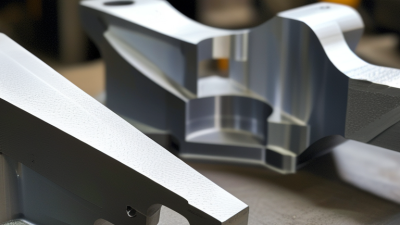
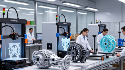
Metal 3d printed parts are engineered components created through layer-by-layer metal additive manufacturing. Unlike machined parts, they grow from digital models instead of solid blocks. A laser or electron beam selectively melts metal powder or wire. Each layer may be thinner than a human hair. The process can produce internal channels, lattice structures, and lightweight shapes that traditional tools cannot easily reach.
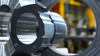
The workflow begins with material selection, design preparation, and process planning. Common alloys include stainless steel, titanium, aluminum, and nickel-based materials. Engineers then build the component inside a controlled chamber. Heat treatment, support removal, machining, and surface finishing often follow printing. Every stage affects dimensional accuracy and performance. Powder condition matters, too. Contamination can weaken a part before anyone sees the problem.
Reliable manufacturers document machine settings, material batches, and inspection results. They may use standards such as ISO/ASTM 52900, alongside application-specific quality systems. Visual checks, dimensional measurement, computed tomography, and tensile testing help verify critical features. Certification requirements depend on the industry and intended use. A medical implant demands different evidence than a prototype bracket.
The technology is powerful, but it is not effortless. Warping, porosity, residual stress, and rough surfaces still require careful control. A beautiful print can fail under repeated loading. That detail deserves attention. Understanding metal 3d printed parts means examining both their design freedom and their manufacturing limits. This guide explains how they are made, tested, and improved for dependable real-world use.
What Metal 3D Printed Parts Are and How They Differ
What Are Metal 3D Printed Parts and How Are They Made?
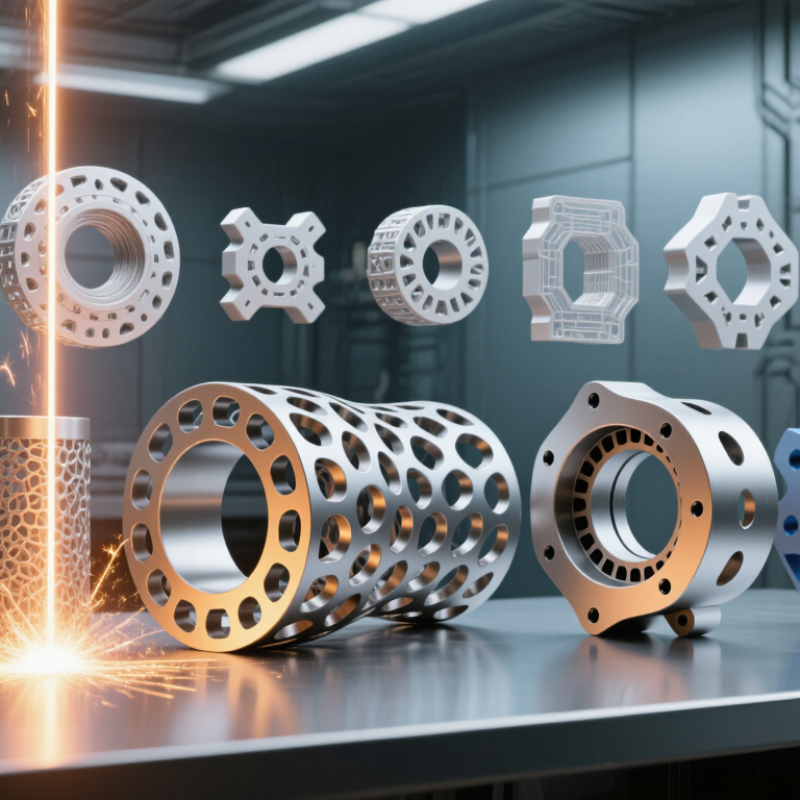
Metal 3D printed parts are components formed layer by layer from metal powder or wire. Unlike cast or forged parts, they begin as digital models. A machine selectively melts, binds, or deposits material to build complex shapes. Common methods include laser powder bed fusion, directed energy deposition, and binder jetting. Some parts leave the machine nearly finished. Others require heat treatment, machining, polishing, or inspection.
Their main difference is design freedom. Engineers can create internal channels, lattice structures, and lightweight forms that conventional tooling may struggle to produce. This matters in aerospace, medical devices, energy systems, and low-volume industrial production. The Wohlers Report 2024 valued the global additive manufacturing industry at approximately $20.0 billion in 2023, showing that these parts have moved beyond laboratory trials. Yet market growth does not remove technical limits.
Metal printed parts can show rough surfaces, residual stress, dimensional variation, or hidden porosity. Build direction also affects strength and fatigue behavior. That assumption is risky. A part that looks accurate may still need computed tomography, density testing, or tensile evaluation. Industry data from the ASTM Additive Manufacturing Center of Excellence repeatedly emphasizes process qualification and standardization as adoption barriers. In practice, material traceability, powder handling, machine calibration, and post-processing often determine reliability more than the printer alone. The boundary between “printed” and “finished” remains imperfect.
What Are Metal 3D Printed Parts and How Do They Differ?
Metal 3D printed parts are components built layer by layer from metal powder or wire. Their material density depends mainly on the alloy selected: aluminum and titanium are lighter, while stainless steel and nickel alloys are denser. The values shown are nominal room-temperature densities for commonly used metal 3D printing alloys; actual printed-part density can vary slightly with composition, process parameters, and internal porosity.
Which Metals and Alloys Are Used in Metal 3D Printing
Metal 3D printed parts are built layer by layer from carefully controlled powders or wires. The alloy choice often matters more than the printer itself. Stainless steel is widely used for corrosion resistance and practical cost. Tool steel suits molds, cutting components, and wear-heavy applications. Aluminum alloys reduce weight, while titanium alloys offer high strength with low density. Ti-6Al-4V remains a common aerospace and medical-grade option. Nickel-based superalloys tolerate heat, although they are harder to print and machine. Cobalt-chrome supports demanding wear and temperature conditions. Copper is attractive for thermal performance, but its reflectivity makes processing more difficult.
Powder bed fusion usually uses lasers or electron beams to melt metal powder. Directed energy deposition feeds wire or powder into a focused heat source. Binder jetting forms a shape first, then sinters it in a furnace. According to the Wohlers Report 2024, the global additive manufacturing industry reached about 20 billion dollars in 2023, growing 13.5 percent. Metal printing represents a major industrial share, especially in aerospace, energy, tooling, and healthcare. However, market growth does not guarantee equal material quality.
Small details matter. Powder size distribution, oxygen levels, moisture, and recycling history can change porosity and surface finish. Heat treatment may relieve stress and improve strength, but it can also distort thin walls. ASTM and ISO standards help define testing methods, yet qualification remains application-specific. A material datasheet is not a guarantee. Real parts need inspection, process records, and mechanical testing. I have found that designers often underestimate post-processing. The printed shape is only one stage.
Where Metal 3D Printed Parts Are Used and Evaluated
Metal 3D printed parts are built layer by layer from metal powder or wire. Heat fuses each layer into a planned shape. Common methods include powder bed fusion and directed energy deposition. After printing, parts may need support removal, heat treatment, machining, and surface finishing. These steps strongly affect final performance.
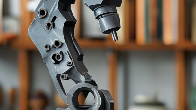
Manufacturers use these parts for lightweight aircraft brackets, medical implants, energy components, and complex tooling. Internal channels can improve cooling, but hidden defects remain possible. Evaluation usually begins with dimensional inspection and surface roughness measurements. Density checks, CT scanning, tensile tests, and fatigue tests reveal deeper problems. Engineers also review powder quality, build direction, heat treatment, and production records. A part may look accurate while containing pores inside. That is why visual inspection alone is weak evidence. Material certificates and repeatable test results support more reliable decisions.
Tips: Match the test method to the part’s real duty. Check thin walls carefully. Record every post-processing step. Do not trust attractive surfaces too quickly. In practice, inspection plans sometimes miss small features, especially near supports. A second review can expose assumptions that seemed reasonable but were never properly tested.